

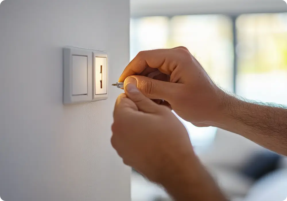
Few minor home improvements provide the immediate visual and tactile upgrade of replacing an old, yellowed light switch. Beyond aesthetics, modern switches offer smoother mechanical operation, improved electrical contact reliability, and support for modern lighting technologies like dimmable LEDs and smart home automation.
Swapping a switch is often the first DIY electrical project a homeowner tackles, but working with line voltage requires respect, systematic preparation, and a strict adherence to safety protocols. A loose connection or a misidentified wire can cause persistent flickering, damage sensitive fixtures, or create a serious fire hazard. This guide walks you through every stage of the process, from mapping your electrical box to securing the final faceplate screw.
Understanding What Lies Behind the Wallplate
Before reaching for a screwdriver, you need to understand the electrical ecosystem inside a standard electrical box. In typical North American residential electrical systems, lighting circuits operate at 120 volts alternating current (AC).
A standard single-pole switch functions as a simple mechanical gatekeeper on the hot conductor. When you flip the switch on, internal contacts close to allow current to travel through the light fixture; when flipped off, the contacts open, severing the path of the electricity.
In homes wired after the mid-1970s using non-metallic sheathed cable (commonly referred to by the brand name Romex), you will typically find three types of wires inside the junction box:
-
Hot Conductors (Usually Black or Red): These carry electrical current from the breaker panel to the switch (the line) and from the switch to the fixture (the load or switch leg).
-
Neutral Conductors (White): These complete the electrical circuit back to the panel. On standard mechanical switches, neutral wires are rarely attached to the switch itself; instead, they are spliced together with a wire nut deep in the back of the box. However, modern smart switches require a neutral connection to power their internal radios and microprocessors.
-
Ground Conductors (Bare Copper or Green): These provide a safe return path for stray current in the event of an electrical fault, tripping the breaker rather than energizing the metal switch yoke or wallplate screws.
Homes built before 1970 may present older two-wire cables lacking an equipment grounding conductor, metallic conduit systems that use the metal pipe as the ground path, or cloth-sheathed wiring with brittle rubber insulation. Identifying what you have before taking anything apart is critical to choosing the correct replacement device.
Tools and Materials You Need
Having the right tools within arm’s reach ensures you do not take shortcuts when the power is off. Assemble these items before you begin:
-
Dual-range non-contact voltage tester: Essential for confirming the circuit is dead before touching exposed copper.
-
Insulated screwdrivers: A standard #2 Phillips, a 1/4-inch flathead, and a #1 or #2 square drive (Robertson) bit, which fits modern terminal screws far better than a Phillips bit.
-
Wire strippers and cutters: Sized for 14 AWG and 12 AWG solid copper wire.
-
Needle-nose pliers: For bending clean, professional hook loops on conductor ends.
-
New switch: Rated appropriately for the circuit (15-amp or 20-amp, matching your breaker rating).
-
Wire connectors (wire nuts or lever nuts): Sized properly for the gauge and count of your conductors.
-
Flashlight or battery-powered headlamp: You will be cutting power to the room, so overhead lighting will not be available.
Step 1: De-Energize the Circuit at the Panel
Never rely on the wall switch itself to turn off power to the box. A switch only interrupts the hot path downstream; the line wire entering the box remains fully energized and hazardous.
Locate your home’s main service panel. Identify the circuit breaker controlling the room or lighting group you plan to work on and switch it firmly to the OFF position. If your panel uses older screw-in fuses, unscrew the corresponding fuse entirely and set it aside.
If your panel schedule is poorly labeled, turn the light switch on first, have a partner watch the light, and switch breakers until the light turns off. Once the light goes dark, resist the urge to assume the box is safe. Electrical boxes often share conduits, feed through to adjacent outlets, or contain multiple circuits. Always verify independently.
Step 2: Test and Verify Zero Voltage
Remove the existing wallplate by backing out the small oval-head screws. Next, remove the two long mounting screws securing the switch yoke to the junction box. Carefully grasp the metal mounting ears and pull the switch straight out from the wall, extending the conductors so the side terminals are accessible. Keep your fingers clear of bare screw terminals and copper conductors during this extraction.
Now perform a three-point test with your non-contact voltage tester:
-
Test the sensor tip against a known live outlet or cord in another room to confirm the tester is working properly.
-
Place the tester tip against every wire, screw terminal, and splice inside the electrical box. Test both side terminals of the switch and any bundled wires in the back.
-
Test the sensor against the known live source again to ensure the tool’s batteries did not fail during the measurement.
The tester must remain silent and unlit at every point inside the electrical box. If the tester lights up or chirps anywhere inside the box, a second live circuit is present, or you switched off the wrong breaker. Stop immediately and locate the remaining live circuit at the panel before proceeding.
Step 3: Document the Existing Wiring
Before disconnecting a single wire, use your smartphone to take multiple well-lit photos from different angles. Pay close attention to which wire connects to which terminal.
If you are replacing a standard single-pole switch, you will typically see two brass or black terminal screws on the side and a green grounding screw at the top or bottom. It does not matter which hot wire goes to the top or bottom terminal on a standard mechanical toggle switch, but on dimmers, motion sensors, and smart switches, identifying the line (incoming power) versus the load (outgoing power to the fixture) is essential.
If the existing switch has three brass or dark screws plus a green ground screw, you are dealing with a three-way switch controlled from two locations. In this scenario, label the wire connected to the odd-colored screw (typically marked “common” or stained dark) with a piece of electrical tape before removing it. Failing to identify the common wire on a three-way switch is the most common reason replacement switches fail to operate correctly.
Step 4: Disconnect the Old Switch and Prep the Leads
Loosen the terminal screws counter-clockwise and unhook the wires from the old switch. If the previous installer used the push-in “backstab” holes on the rear of the switch, do not yank the wires out by force. Insert a small precision flathead screwdriver or stiff paperclip into the release slot next to the hole to free the wire, or clip the wire flush with the back of the switch and re-strip it if enough slack exists.
Backstab connections rely on tiny internal spring-steel clips that lose tension over decades of thermal expansion and contraction. They are a frequent cause of intermittent power loss and high-resistance heat buildup. High-quality replacement switches feature side screw terminals or clamp-style back-wiring (where a screw tightens a flat brass plate against the wire).
Inspect the stripped ends of the wires:
-
If the copper is nicked, oxidized, or bent out of shape, snip off the damaged portion.
-
Use wire strippers to expose approximately 5/8 inch to 3/4 inch of fresh copper, matching the strip gauge molded into the back of your new switch.
-
Using the tips of your needle-nose pliers, form a smooth, uniform U-shaped hook in the bare copper end of each wire.
Step 5: Wire the New Switch
When connecting wires to screw terminals, the orientation of the copper hook matters. Always loop the wire hook clockwise around the screw shank. As you tighten the screw clockwise, the rotational friction draws the wire loop tighter into the screw shank rather than opening the loop outward.
Follow this sequence for the most secure and orderly installation:
Attach the Ground Wire First
Connect the bare copper or green insulated ground wire to the green grounding screw on the switch yoke. If your electrical box is metal and fed by grounded metal conduit or armored cable, the box itself may be grounded. In that case, pigtail a short green or bare wire from a grounding screw threaded into the back of the metal box to the switch’s ground screw.
Connect the Hot Conductors
Hook the line and load conductors around the side brass terminals. Tighten the screws firmly with a screwdriver that fits the screw head snugly. The screw should clamp down securely on solid copper; no insulation should be trapped under the screw head, and no more than 1/16 inch of bare copper should extend past the perimeter of the screw.
Wire the Neutral (If Applicable)
If you are installing a standard mechanical toggle or rocker switch, leave the bundle of white neutral wires tucked neatly in the back of the box untouched. If your new switch is a smart device or digital timer that requires a neutral connection, remove the wire nut from the existing neutral bundle, add the new switch’s neutral lead, twist on an appropriately sized wire nut firmly, and ensure no bare copper strands protrude from beneath the connector skirt.
Step 6: Fold the Wires and Mount the Device
Shoving wires haphazardly into an electrical box can crack older wire insulation, loosen wire nuts, or short an uninsulated ground wire against a hot terminal screw.
Use an accordion-style fold to stow the conductors cleanly:
-
Push the neutral bundle into the deepest recess of the box.
-
Push the bare ground wire toward the bottom or back of the box, ensuring it stays well clear of the side terminal screws.
-
Gently fold the hot conductors back and forth like an accordion bellows, using the flat of your thumb to guide them into the box cavity.
-
Push the switch yoke flat against the face of the electrical box.
Thread the top and bottom mounting screws into the box’s threaded mounting ears. Before tightening them completely, check that the switch is sitting plumb. Most switch mounting holes are slotted, allowing you to tilt the switch slightly left or right before locking it in place. Tighten until the yoke rests flush against the drywall or box edge without bowing the mounting strap.
Step 7: Restore Power and Perform the Operational Test
Before installing the decorative plastic faceplate, step back from the box, keep hands and tools away from the open device, and restore power at the main electrical panel.
Return to the room and flip the switch:
-
Does the fixture illuminate instantly without buzzing or flickering?
-
If installing a dimmer, does the dimming slider adjust smoothly across the full brightness range without causing LED bulb strobing?
-
If installing a three-way switch, does the light turn on and off correctly from both switch locations?
Once you have verified normal operation, turn the circuit breaker back off if you prefer maximum caution, align the wallplate, and drive the faceplate screws until snug. Do not overtighten faceplate screws; modern thermoplastic or nylon plates can warp, and traditional brittle polystyrene plates will crack down the center under excessive torque. Align the screw slots vertically for a clean, professional finish. Turn the breaker back on to complete the project.
Common Pitfalls to Avoid
Even straightforward switch replacements can run into snags if small details are overlooked. Keep these principles in mind:
-
Mismatched Amperage Ratings: Standard residential lighting circuits typically run on 15-amp breakers wired with 14 AWG copper wire. However, if your lighting circuit shares a 20-amp breaker wired with heavier 12 AWG wire (common in kitchens, bathrooms, and garages), your replacement switch must be rated for 20 amps. A 15-amp switch installed on a 20-amp circuit violates the National Electrical Code.
-
Touching Hot Terminals with Bare Ground Wires: When folding wires into shallow or crowded junction boxes, a stiff bare copper ground wire can shift toward the side terminal screws. If a ground wire contacts a hot terminal screw when power returns, it creates an immediate short circuit, tripping the breaker with a loud pop. Wrapping two layers of high-grade vinyl electrical tape around the perimeter of the switch body covering the screw terminals adds a valuable layer of insulation against accidental contact.
-
Overcrowded Electrical Boxes: Older junction boxes were often smaller than modern code allows. If you are retrofitting a bulky smart switch or dimmer into a small metal box, check that the device fits without forcing wires against sharp metal edges. If the box exceeds its allowable wire-fill capacity, you may need to upgrade to a deeper box or install an extension ring.
Critical Red Flags That Warrant an Electrician
While replacing an existing light switch is well within standard DIY capabilities, certain pre-existing conditions demand professional intervention:
-
Solid Aluminum Wiring: If you open the box and find silver-colored wires dating from the mid-1960s to mid-1970s, do not install a standard hardware-store switch. Standard switches are rated for copper only (marked “CU ONLY”). Connecting aluminum wire to standard brass terminals leads to galvanic corrosion, loose joints, and high fire risk. Aluminum circuits require specialized CO/ALR-rated devices or specialized connector splices installed by a qualified electrician.
-
Deteriorated or Crumbly Cloth Insulation: In homes built prior to 1950, older rubber-and-fabric insulation can dry out over time. If touching the wire causes the cloth or rubber insulation to flake away and expose bare copper inside the cable sheath, stop immediately. Brittle wiring must be inspected and remediated before installing new devices.
-
Absence of Grounding with Metal Wallplates: If your box lacks an equipment ground wire and the conduit is not grounded, installing a decorative metal wallplate creates a safety hazard. If a hot wire ever touches the metal plate, the entire plate becomes energized with no ground path to trip the breaker. On ungrounded circuits, use only non-conductive plastic wallplates.
Taking your time, treating every conductor with caution, and respecting the basic mechanics of electrical connections guarantees a modern, clean light switch upgrade that looks great and runs safely for decades to come.